Flashing an ESP8266-01
Flashing a ESP8266? Follow this guide written by a beginner for beginners.

I’ve been working on integrating a Nova PM sensor with an ESP8266-01 controller to send some AQI data to an API hosted on the internet. I have very little experience working with circuit boards, so it took me some time to figure out the nitty-gritties and nuances of working with these devices. There are multiple variations of ESP8266 boards available, this tutorial focuses on the ESP8266-01 board which looks like this.
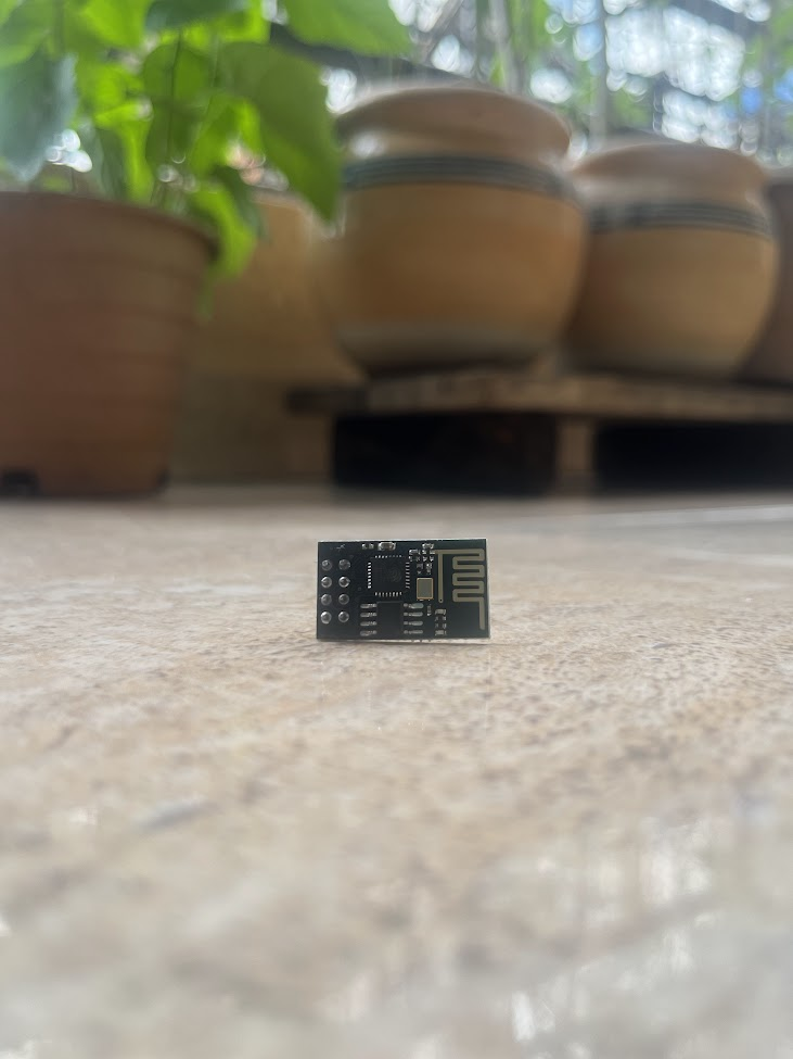 ESP8266-01
Here’s a list of things you’d need to flash a ESP8266-01
- ESP8266-01
- USB TTL Serial Converter
- Breadboard
- Jumper cables (In this case, Female to Male [ESP8266/USB TTL to breadboard] and Male to Male)
- Push Button (makes life easier to switch to flash or normal mode)
The USB TTL device comes labelled with appropriate pins.
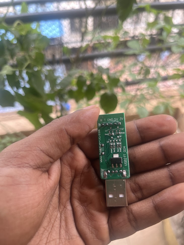 USB TTL device
A breadboard is used here since the ESP8266 has multiple pins would require to be connected to the 3v and the Ground. A breadboard is divided into multiple rows and columns. Read this if you want to understand in detail about breadboards (solderless)
Use the following diagram as a reference while connecting the cables.
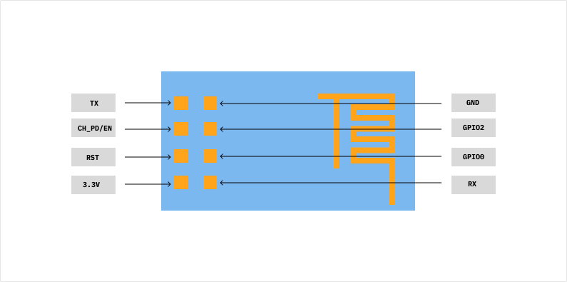 ESP8266-E01 diagram
Wiring instructions
- USB TTL R(x) —> ESP8266 T(x)
- USB TTL T(x) —> ESP8266 R(x)
- USB TTL 3.3v —> ESP8266 3.3v
- USB TTL GND —> ESP8266 GND
- USB TTL 3.3v —> ESP8266 CH_PD/EN
- USB TTL GND —> ESP8266 GPIO0
ESP8266 circuit diagram
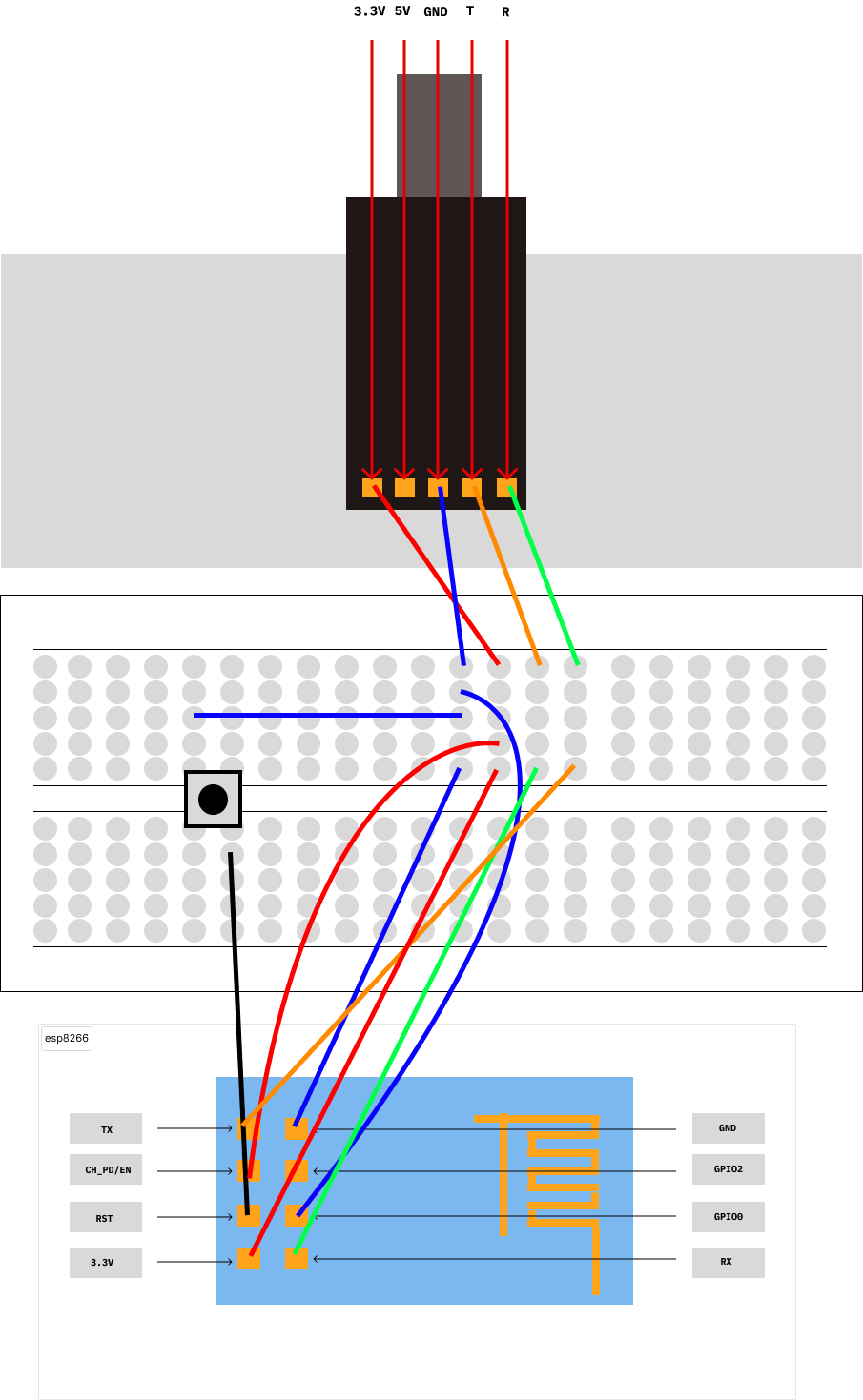 USB TTL ESP8266 breadboard circuit
Legend:
- Green - RX
- Orange - TX
- Red - 3.3v
- Blue - GND
- Black - RST
- Grey Square with black circle - Push button
To enable bootloader/flash mode on the ESP8266, the RST pin needs to be low when all the above wires have been configured. There are two ways you can achieve this.
Method 1
- Place a push button on the breadboard and draw a cable from the GND to one corner of the button.
- Connect the RST pin of the ESP8266 to the other corner of the button such that a line between the corners of the button should be a diagonal.
- Connect the USB TTL to a computer, ensure you have the correct device and port selected on your IDE (I was using Arduino IDE), push the reset button and flash away!
If this doesn’t work, you might have to start flashing from your IDE and then push the reset button for the upload to work.
Method 2
- After connecting all cables, connect the RST pin to the GND row on your breadboard and then connect the USB TTL device to your computer.
- Start flashing on your IDE and immediately remove the RST pin from the breadboard.
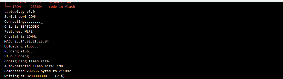
If everything’s in your favour, you’d see something like this on your IDE console.